Configure Tunnels with Cisco Secure Firewall
Cisco Secure Firewall is a family of threat-focused next-generation firewalls. It can be managed centrally through Cisco Secure Firewall Management Center or through the on-box manager Secure Firewall Device Manager (FDM). This guide covers the steps to configure site to site VPN between FTD devices and Secure Access through the Cisco Secure Firewall Management Center centralized manager.
Until version 6.7, FTD only supports policy-based VPN (Crypto-map). Version 6.7+ supports Virtual tunnel interface (VTI), version 7.1+ supports IKE identity and policy-based routing (PBR) through graphic interface.
Table of Contents
- Configure Secure Firewall Policy-based VPN
- Configure Secure Firewall VTI, PBR, and Per Tunnel Identity
- Troubleshooting
Configure Secure Firewall Policy-based VPN
The Secure Firewall configuration process consists of the following steps.
- Add Network Object
- Add Traffic Selector ACL
- Configure Site-to-Site VPN
- Configure NAT Policy
- Configure Access Policy
To start the configuration, log in to your Cisco Secure Firewall Management Center web interface at its IP address or FQDN; for example, https://FMC_IP_OR_FQDN.
Configure Tunnels in Secure Access
Secure Firewall authenticates to the Secure Access IPsec headend by using a Pre-Shared Key (PSK) and IKEv2 IP identity.
Follow the steps in Add Network Tunnel Group to add an FTD device to Secure Access.
The new tunnel appears in Secure Access with a status of UnEstablished. The tunnel status is updated once the first IKEv2 INIT message containing the tunnel identity is received in one of the Secure Access data centers.
Note: Secure Access does not support dynamic IP addresses for ASA and Secure Firewall devices.
Add Network Object
Create a network object type “Group”. You will use this object in NAT configuration as well as in the Access Control List (ACL) in the IKEv2 traffic selector. Using a group object simplifies the task of bypassing encryption and provides NAT for the bypassed traffic.
Note: Public IP traffic from SIG users will appear to come from the address ranges 146.112.0.0/16 and 155.190.0.0/16. Depending on your organization, you may be required to inform service providers that you access through the Secure Access service of these additional IP address ranges. For example, some service providers require prior knowledge of the IP address ranges used before allowing access to their service.
- Navigate to Objects > Object Management > Network > Add Network > Add Group.
- Add the Secure Access resolvers IP address so the DNS queries are not sent through the tunnel.
Currently, if the DNS queries are sent through the tunnel it will be NATed to 146.112.0.0/16 IP range and queries will not be linked to the user's dashboard. By bypassing the traffic to the Secure Access resolvers it is possible to add a public IP address to the dashboard (network deployment) and retrain DNS visibility and enforcement capabilities.
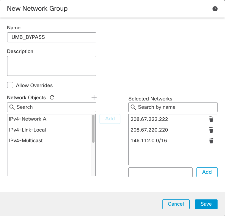
- Optionally, add 146.112.0.0/16 as a network. Web traffic from endpoints with PAC file or Cisco Secure Client as well as proxy chaining traffic can then go outside the IPSec tunnel and achieve higher throughput.
Add Traffic Selector ACL
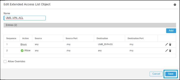
This ACL is used in the IKEv2 security association negotiation as well as when Secure Firewall makes decisions about when to encrypt traffic. It does not encrypt traffic denied in the ACL when the deny statement comes before the permit statement.
- Navigate to Objects > Object Management > Access List > Extended > Add Extended Access List.
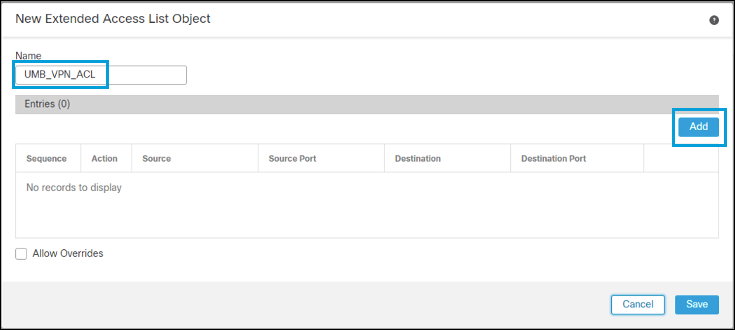
- Enter a name for the ACL and then click Add to add the Access Control Entries (ACE).
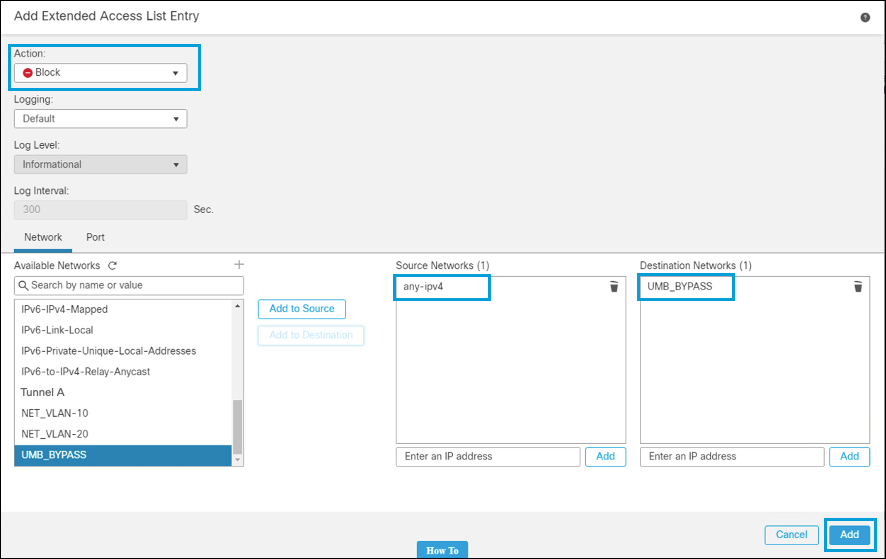
a. The first entry denies traffic to the network object type group containing the Secure Access resolvers. Optionally, traffic to the
146.112.0.0/16and155.190.0.0/16subnets can also be denied.
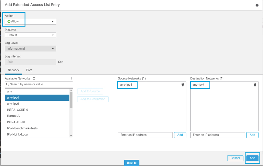
b. The second entry allows traffic from any IPv4 address to any IPv4 address. This is also the entry IKEv2 uses to negotiate the IPSec Security Association (traffic selector).
- After you have added the entries, click Save.
Configure Site-to-Site VPN
You can now configure the site-to-site VPN.
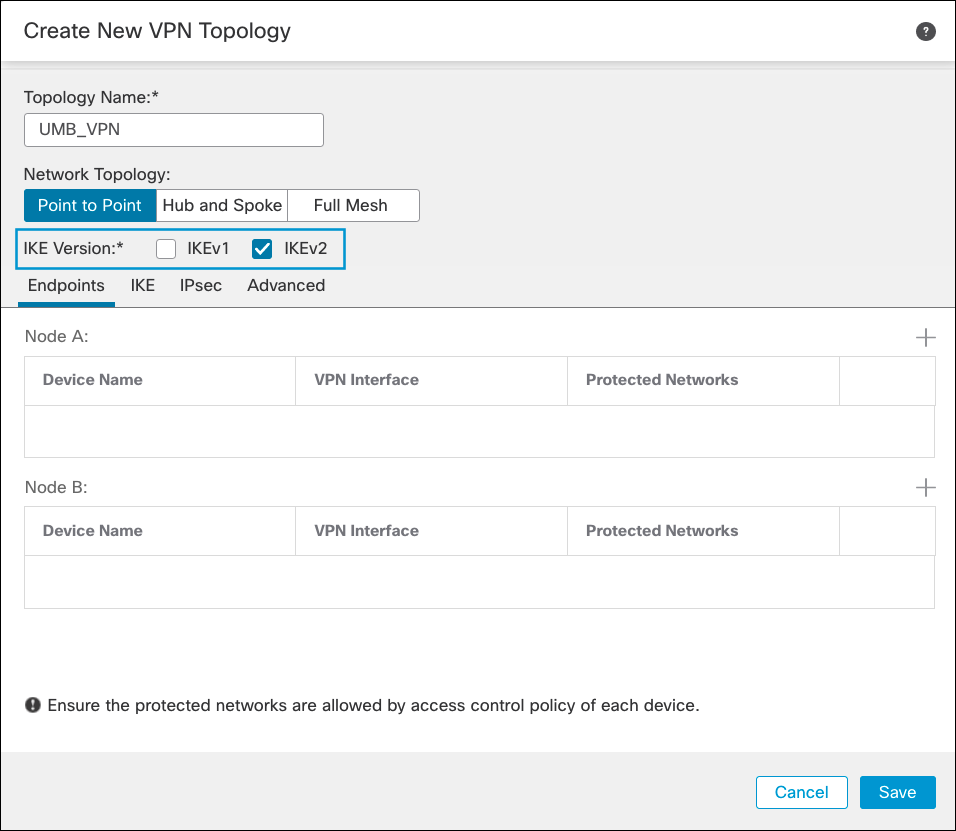
- Navigate to Devices > VPN > Site to Site > Add VPN > Secure Firewall Threat Defense Device.

- Enter a name for the topology. Check IKEv2 box (Secure Access supports IKEv2 only). For more information about supported protocols, see Supported IPSec Parameters.
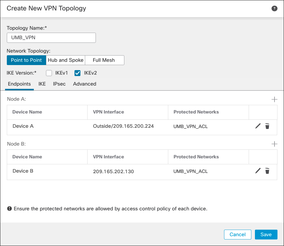
- Add two peers: the local peer (FTD device) and the remote peer (Secure Access).
a. Click Add for Node A and select the FTD device as the local peer and the interface sourcing the IPSec connection. The IP address is automatically populated.
b. Under Protected Networks, select Access List (Extended), and then select the ACL you created in the Traffic Selector ACL. Click OK.
c. Click Add for Node B to add the remote peer.
d. Select Extranet and enter a name. Select Static, and enter one of the Secure Access datacenter IP addresses. Then select the same ACL, then click OK.
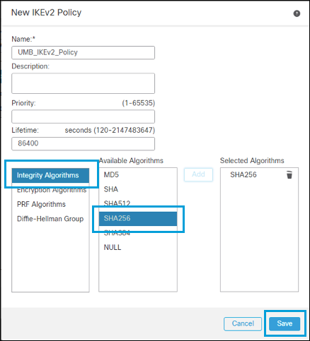
- Click the IKE tab to add a new IKEv2 Policy containing the desired crypto algorithms. For more information about encryption supported by Secure Access, see Supported IPsec Parameters.
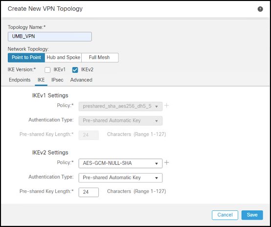
- Enter a name for the IKEv2 policy, then select the parameters from the Supported IPsec Parameters.
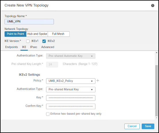
- After saving the IKEv2 Policy, select it. Choose Pre-shared Manual Key from the Authentication drop-down menu and enter the key.
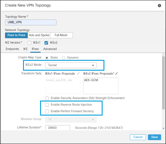
- Under IPSec Configuration, add a new IKEv2 IPsec Proposal with your crypto algorithms or select an existing profile. Select Tunnel for IKEv2 Mode and uncheck Enable Reverse Route Injection and Enable Perfect Forward Secrecy.
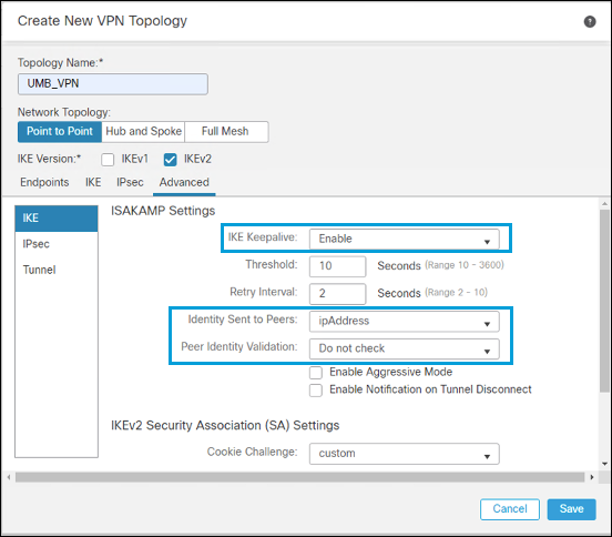
- In the Advanced tab under IKE, enable IKE Keepalive. Select ipAddress as the Identity Sent to Peers, and disable Peer Identity Validation.
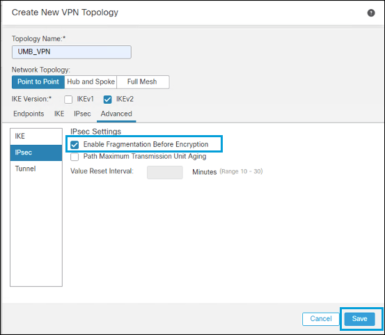
- Under IPSec, select Enable Fragmentation Before Encryption, then click Save.
Configure NAT Policy
If a NAT policy currently exists in the Secure Firewall device, this policy must be changed to exempt traffic going through the tunnel from being NATed. Secure Access requires the source of the connection to be the client’s original private IP address — the public IP is not currently supported.
If you use the public IP in your internal network, you must NAT the traffic to a private IP address pool before sending the traffic to Secure Access, as most of the traffic goes through the Secure Access IPSec tunnel. It is easier to create NAT for the traffic not going through the tunnel and use no NAT for all other traffic.
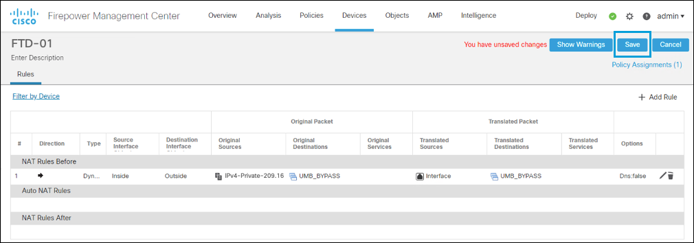
In this example, the network object containing the Secure Access resolvers' IP address is referred to in the NAT statement. All traffic sourced from the internal network with a destination matching the network object will have the source IP NATed to the firewall interface address. All other traffic does not match the NAT statement, and so is forwarded to Secure Access without being NATed.
- In Cisco Secure Firewall Management Center, navigate to Devices > NAT > New Policy > Threat Defense NAT.
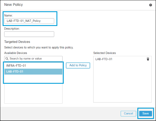
- Enter a name, then select the FTD device to apply the policy. Click Save.
- Click Add Rule.
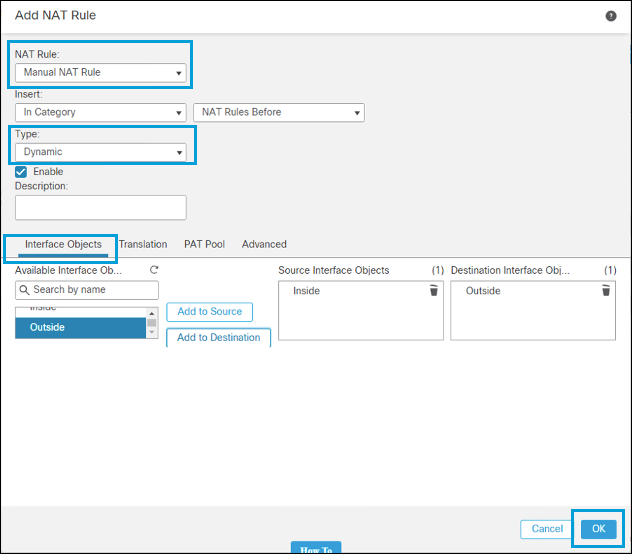
- Select Manual for NAT Rule, then select Dynamic for type. In Interface Objects, choose Inside for the Source and Outside for Destination.
- Under Translations, select a network object containing the internal subnet as the Original Source. Specify the Secure Access bypass network object you previously created as the Original Destination.
This object contains the Secure Access resolvers' IP address, as well as (optionally) the
146.112.0.0/16and155.190.0.0/16networks, plus any other traffic you may want to exempt from the tunnel. Using this object facilitates the configuration, because when hosts and subnets are added or removed from the object, both the IPsec traffic selector and NAT statement are updated.
- Select Destination Interface IP as the translated source, and the same object as the translated destination.
This ensures that the internal network is NATed to the interface IP address only when the destination is the network object containing the resolver's IP address. Other destinations do not match the NAT statement.
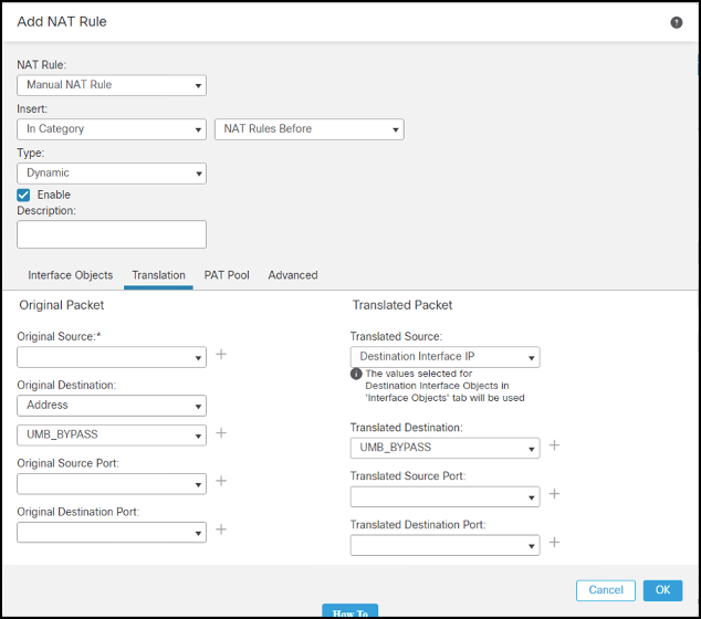
- Click OK, and then click Save. The NAT policy is configured.
Configure Access Policy
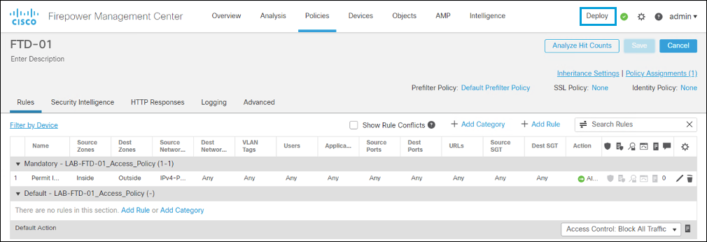
The Access Policy in Secure Firewall combines all the other policies (SSL Decryption, DNS, Pre-filter, Identity). At a minimum, an entry permitting inside traffic going out should exist. In production environments, you normally add more specific access entries.
Deployment Not Automatic
A policy configured in Cisco Secure Firewall Management Center is not automatically applied to FTD devices. The configuration must be enabled by clicking Deploy in the top configuration bar.
Configure Secure Firewall VTI, PBR, and Per Tunnel Identity
At a high level, the Secure Firewall configuration process consists of the following steps.
To start the configuration, log in to your Cisco Secure Firewall Management Center web interface at its IP address or FQDN; for example, https://FMC_IP_OR_FQDN.
Configure Tunnels in Secure Access
From Secure Firewall 7.1+, FTD can authenticate to Secure Access by using a Pre-Shared Key (PSK) and IP or FQDN IKEv2 identity. If the Secure Firewall is behind a NAT device, FQDN identity is the only possible option.
Virtual tunnel interface is available from Secure Firewall 6.7+ with Policy Based Routing (PBR) through FlexConfig. Secure Firewall 7.1+ adds Per Tunnel Identity and Policy Based Routing via graphic interface.
Follow the steps in Add Network Tunnel Group to add Secure Firewall VTI and PBR to Secure Access.
Note: When supported by the device, FQDN is always the preferred option.
The new tunnel appears in Secure Access with a status of UnEstablished. The tunnel status is updated once the first IKEv2 INIT message containing the tunnel identity is received in one of the Secure Access data centers.
Configure Site-to-Site VPN
You can now configure the site-to-site VPN.
- Navigate to Devices > VPN > Site to Site > Add VPN > Secure Firewall Threat Defense Device.

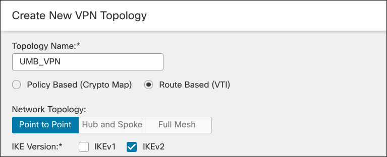
- Enter a name for the topology, select Route Based (VTI), and check IKEv2 box. For more information about supported protocols, see Supported IPSec Parameters.
- Choose a Secure Firewall device from the Device drop-down list for Node A and click Add to add a Virtual Tunnel Interface.
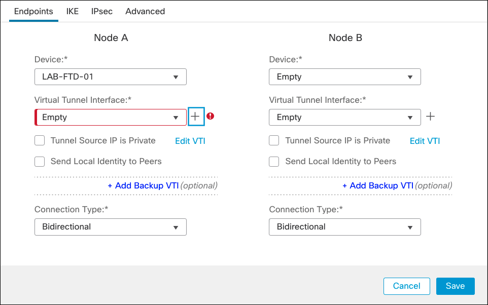
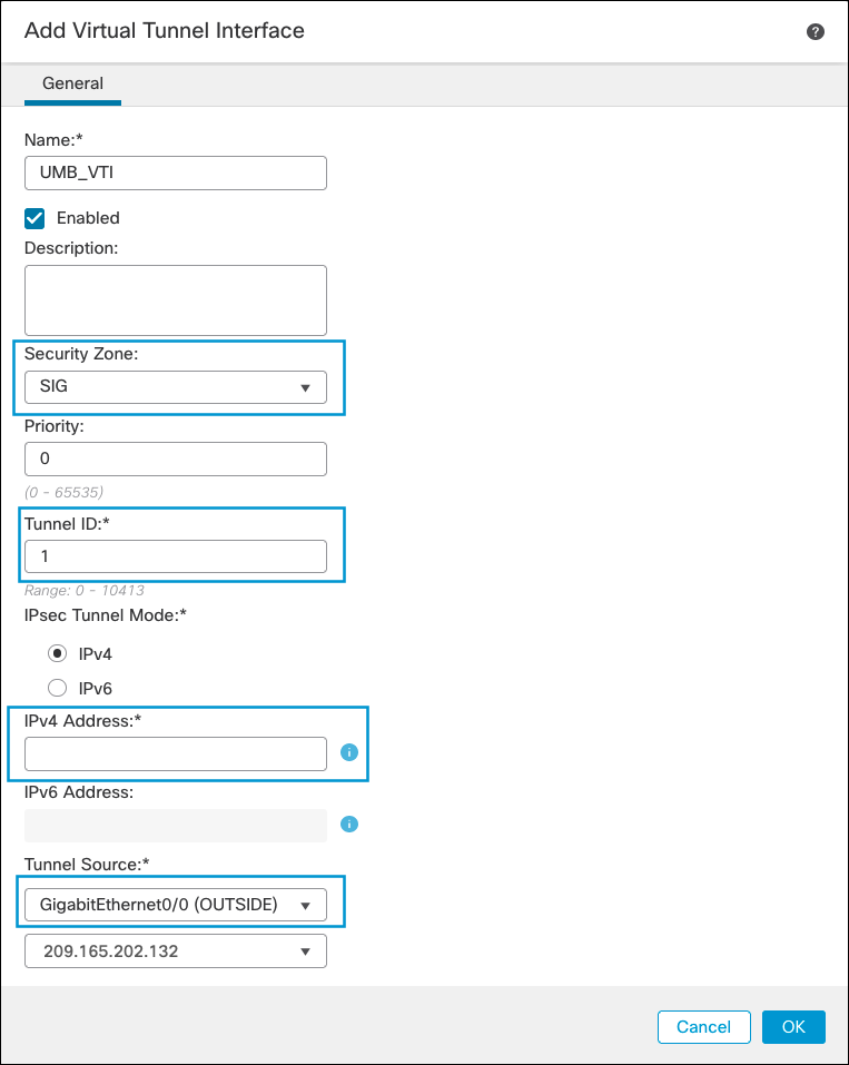
- Enter a name for the VTI, choose an existing Security Zone or create a new for the tunnel, enter a Tunnel ID and an IP address (a /30 subnet to accommodate local device and remote IP), and select the OUTSIDE interface as tunnel source. Then click Ok.
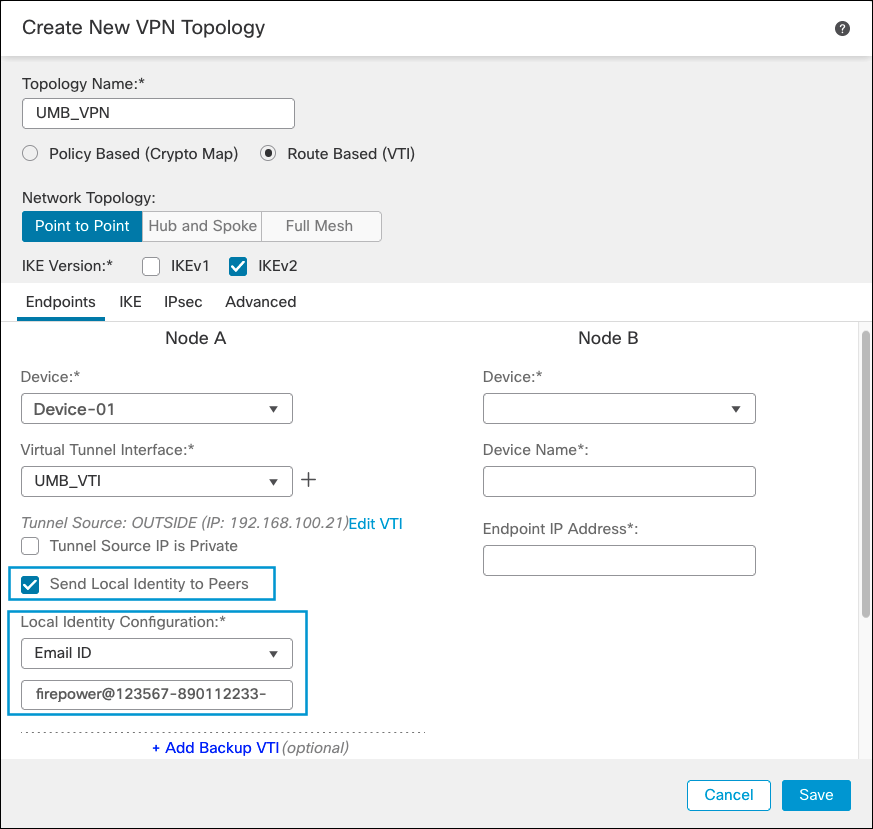
- Select the VTI you just created and check Send Local Identity to Peers.
- Select Email ID from the Local Identity Configuration dropdown.
- Type the FQDN of the previously created tunnel.
IMPORTANT: For greater throughput you can configure multiple tunnels to the same Secure Access network tunnel group. For multiple tunnels, select Key ID from the Local Identity Configuration dropdown, then enter the Key ID for each tunnel, separated by a + sign.
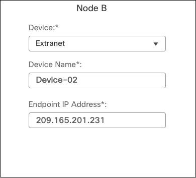
- Under Node B, choose Extranet as the device, enter a name and IP address of a Secure Access data center.
- Enter a name for the IKEv2 policy, then select the parameters from the list.

- After saving the IKEv2 Policy, select it. Choose Pre-shared Manual Key from the Authentication drop-down list and enter the key.

- Under IPSec Configuration, add a new IKEv2 IPsec Proposal with your crypto algorithms or select an existing profile. Select Tunnel for IKEv2 Mode and uncheck Enable Reverse Route Injection and Enable Perfect Forward Secrecy.

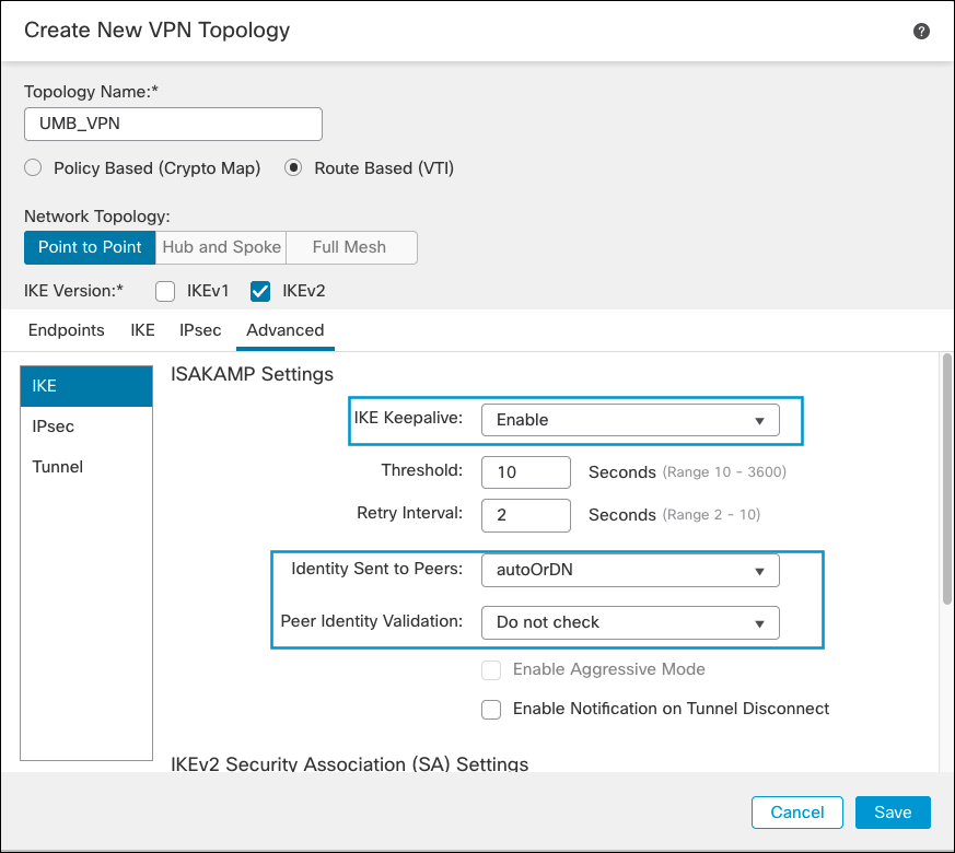
- In the Advanced tab under IKE, enable IKE Keepalive. Select autoOrDN as the Identity Sent to Peers, and disable Peer Identity Validation. Then click Save.
Configure Policy-based Routing
- Navigate to Devices > Device Management and click the name of the device to edit.
- Under Routing > Policy Based Routing, click Add to add a new policy
- Choose the Inside for the Ingress Interface (user’s facing interface where PBR will be applied) and click Add.
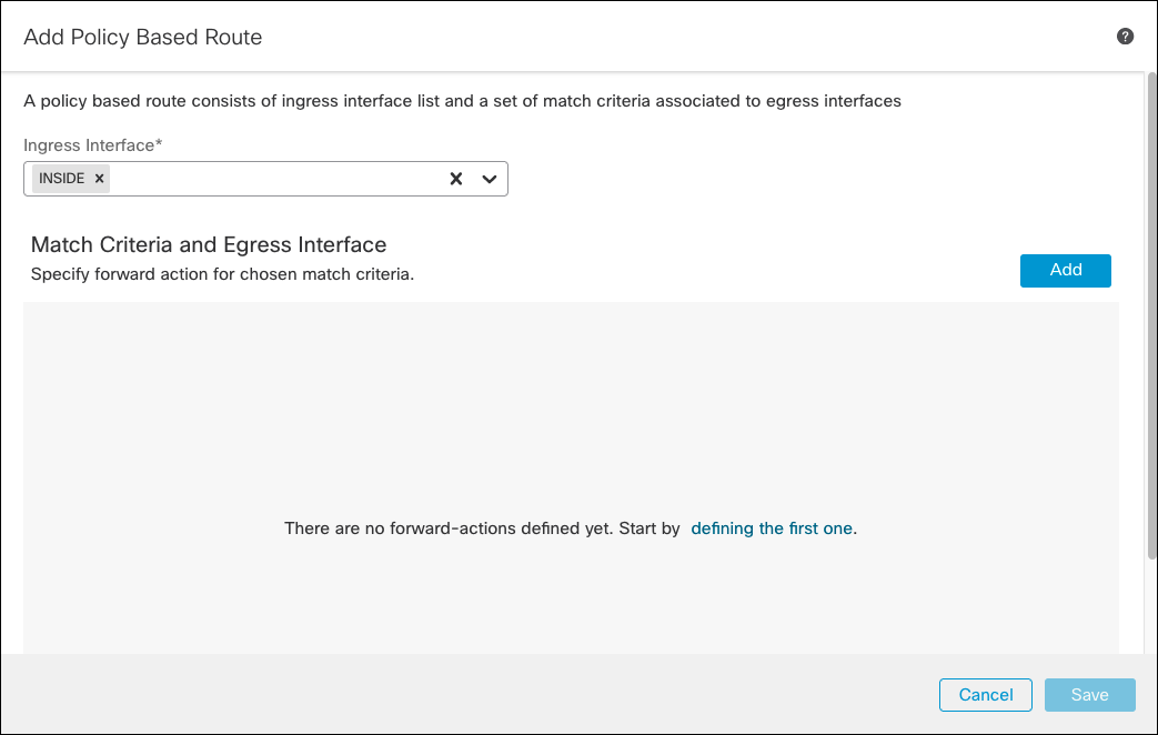
- Choose the existing extended ACL, and click Add.
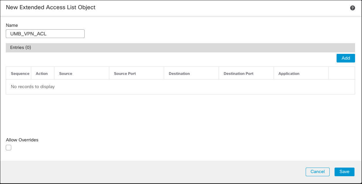
Alternatively, if you are creating a new ACL, enter a name and add Access Control Entries (ACE) matching the traffic that should be redirected to Secure Access.
- Click Save to add the access entries.
- Under Match ACL, choose the newly created ACL and under Send To choose IP Address. Type the IP address in the same subnet previously used for VTI and click Save
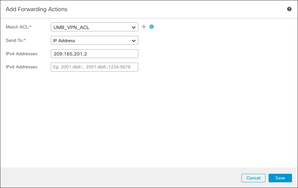
- Click Save to save the configuration and deploy.
Configure Access Policy
If not yet allowed by the access policy, add an access entry allowing traffic from inside the network to the Secure Access tunnel.
Troubleshooting
Cisco Secure Firewall Management Center has a VPN troubleshooting tab where VPN-related events are displayed. By default, only error messages are sent from FTD to Cisco Secure Firewall Management Center, as LINA code (ASA) is responsible for the IPSec tasks the same commands available for troubleshooting the ASA devices are available in FTD.
If you need to send VPN debug messages to Cisco Secure Firewall Management Center, change the logging level in the Platform Settings policy. This policy is configured and added in Devices > Platform Settings. VPN logging to Cisco Secure Firewall Management Center is in the Syslog section of the Platform Settings policy from the Logging Setup tab. It is also possible to send logging messages to other destinations, such as the FTD device internal buffer.
Enable Logging for Debugging
- In Cisco Secure Firewall Management Center, navigate to Devices > Platform Settings.
- Under Basic Logging Settings, add a logging destination.
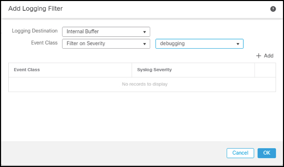
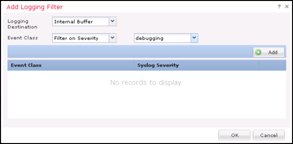
- Under Logging Destinations tab, click Add, then select Internal Buffer (or another logging destination). Set the logging level to Debugging.
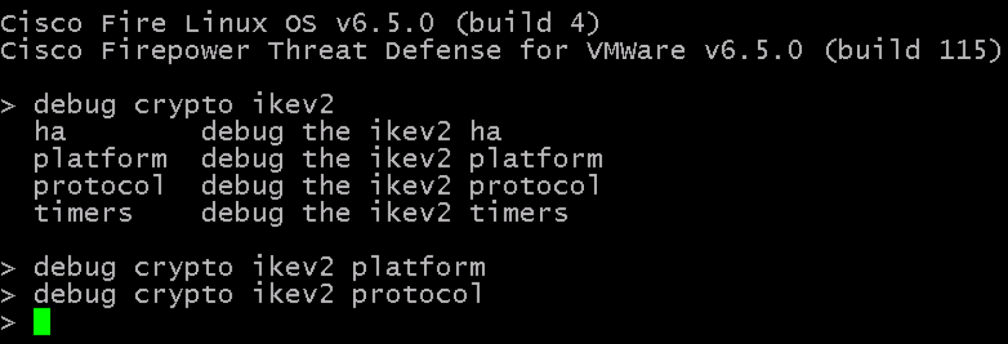
When logging is enabled, you can enable IKEv2 debug, SSH to FTD. Then enter type debug crypto ikev2 platform and debug crypto ikev2 protocol. These two debugging options provide detailed information about IKEv2 negotiation.
- After enabling debugging in the FTD device, return to Cisco Secure Firewall Management Center and navigate to Devices > VPN > Troubleshooting. IKEv2 negotiation debugging information is available.
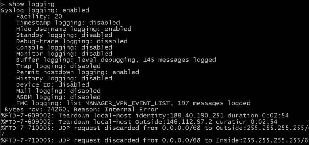
If debug destination internal buffer was configured, going back to the FTD device via SSH is also possible. This enables you to see debug messages in the FTD terminal.
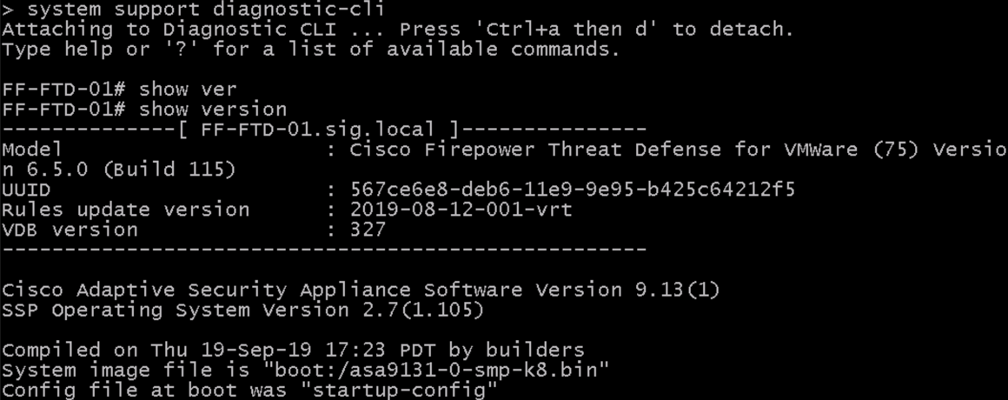
To access the LINE portion of the code, enter the command system support diagnostic-cli.
Configure Tunnels with Cisco Adaptive Security Appliance < Configure Tunnels with Cisco Secure Firewall > Configure Tunnels with Meraki MX
Updated 5 months ago
