Add a Network Tunnel Group
To enable tunnel redundancy and high availability for IPsec tunnels connected to data center hubs, follow the steps to add a network tunnel group to Cisco Secure Access.
Table of Contents
About Network Tunnel Groups
Provisioning high-availability network tunnel groups at a hub site allows a group of tunnels to share a primary and secondary hub. Network devices that are capable of establishing an IPsec tunnel can join a network tunnel group using the credentials created when the tunnel group is deployed.
Each data center hub in a network tunnel group can connect to multiple tunnels. A hub configured for NAT can support up to 100 tunnels. A hub that is not configured for NAT is limited to 10 tunnels.
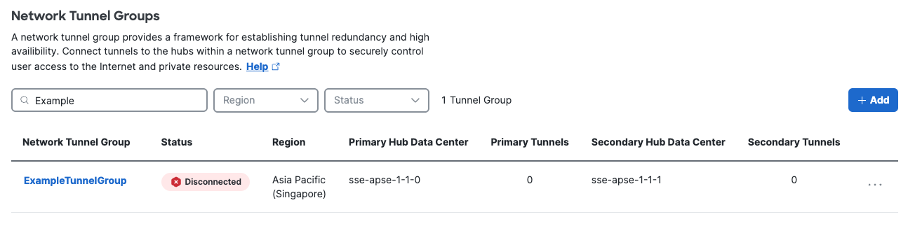
- In Secure Access, configure the attributes of the tunnel group and deploy the tunnel group. Once the tunnel group is deployed, the initial state of the tunnel group changes from Unestablished to Inactive.
- Next, configure primary and secondary tunnels in the network device that sends traffic to Secure Access. Use the deployed tunnel group's attributes to associate the network tunnels to the tunnel group. The network tunnel group attributes required by network devices to establish the IPsec IKEv2 tunnel are: tunnel ID, tunnel passphrase, and IP Address of the Secure Access data center.
- Enable user computers to connect securely to the tunnel and begin to send traffic to Secure Access. Once Secure Access receives and logs traffic from a network tunnel, the tunnel state is considered Active. View the events for the tunnel in the Secure Access Overview and Activity Search.
Prerequisites
- Full Admin role in Secure Access. For more information, see Manage Accounts.
Procedure
Perform the following tasks to add a network tunnel group to Secure Access. Network tunnel groups work to enable tunnel redundancy and high availability for IPsec tunnels connected to data center hubs.
- Step 1 - General Settings
- Step 2 - Tunnel ID and Passphrase
- Step 3 - Routing
- Step 4 - Data for Tunnel Setup
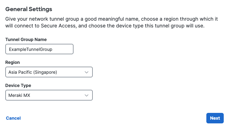
Step 1 - General Settings
- Navigate to Connect > Network Connections > Network Tunnel Groups.
- Click Add.
- Enter the General Settings for your tunnel group:
- Give your tunnel group a meaningful name.
- Choose a Region.
- Choose a Device Type.
- Click Next.
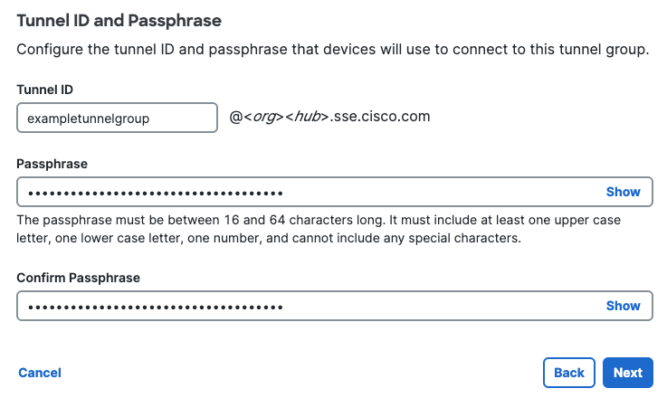
Step 2 - Tunnel ID and Passphrase
Configure the tunnel ID and passphrase that devices will use to connect to this tunnel group.
-
Enter Tunnel ID.
- Tunnel ID may be an email address or a primary and secondary pair of IP addresses.
- Tunnel ID format requirements are as follows for each device type selected in Step 1 - General Settings:
Device Type Tunnel ID Format Meraki MX Email Catalyst SDWAN Email ISR Email ASA Email OR IP address (primary and secondary) AZURE IP address (primary and secondary) FTD Email OR IP address (primary and secondary) Other Email OR IP address (primary and secondary) - Email tunnel ID requires the format <tunnel name>@<org><hub>.sse.cisco.com. Use the name you gave the tunnel group in Step 1 - General Settings.
- IP address tunnel ID requires both a primary and secondary IP address.
-
Enter a tunnel Passphrase between 16 and 64 characters in length. The passphrase must contain at least one upper case letter, one lower case letter, and one number. The passphrase cannot include any special characters.
-
Reenter your passphrase to confirm.
-
Click Next to continue.
Step 3 - Routing
Configure routing options and network overlaps for this tunnel group.
- Check Enable NAT / Outbound only if you determine that the IP address space behind the tunnel group overlaps with other IP address spaces in your network.
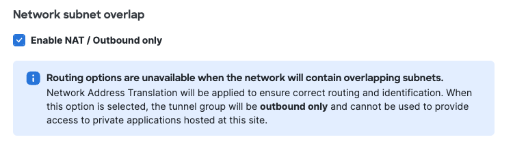
Note: Enabling NAT for outbound traffic disables the routing options described below. Private applications hosted behind these tunnels will not be accessible.
- Choose a Routing option for this network tunnel group.
- Choose Static routing to manually add IP address ranges for this tunnel group. You should add all public and private address ranges used internally by your organization.
Note: Adding a default route in static routing is not supported and can lead to traffic disruptions.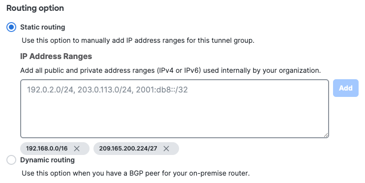
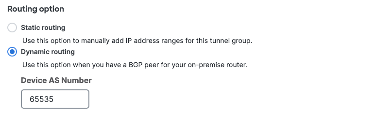
- Choose Dynamic routing when you have a BGP peer for your on-premise router. Enter the router's autonomous system (AS) number.
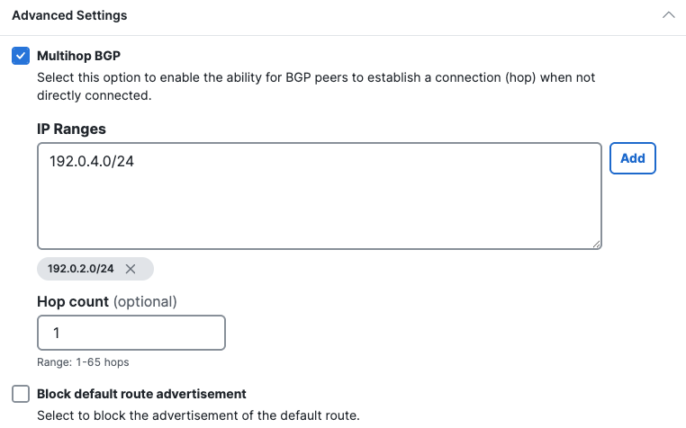
- Expand Advanced Settings for additional dynamic routing options.
- Multihop BGP enables the ability for BGP peers to establish a connection when not directly connected.
- Enter the IP Ranges from where BGP peering sessions will originate, then click Add
- (Optional) Enter the Hop count to limit the number of hops over which the BGP multihop session is established. The range is 1 to 254 hops. The hop count is disabled until IP addresses are entered, with a default value of 1. Note: The hop count equates to the TTL (Time to Live) parameter.
- Block default route advertisement block the advertisement of the default route in dynamic routing mode. Advertising default routes via BGP is not supported and can lead to traffic disruptions.
Step 4 - Data for Tunnel Setup
Review and save the following information for use when setting up your network tunnel devices. This is the only time that your passphrase is displayed.
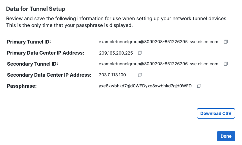
Click Download CSV to save your tunnel setup information. You can use the information to configure and deploy a tunnel in a network device.
What to do Next
Configure Tunnels on a Network Device
- Follow the steps in one of the network device guides to deploy an IPsec tunnel with Secure Access. For more information see Network Tunnel Configuration.
- For redundancy, the network device must connect to both the primary and secondary tunnel. For more information, see Throughput and Multiple Tunnels and Failover for Branch Connections in Secure Access Data Centers.
Verify Tunnel Traffic in Secure Access
After you add a tunnel to Cisco Secure Access and deploy a network tunnel with a compatible network device, check that Secure Access receives and logs traffic from the tunnel.
- Navigate to Overview and find your configured tunnel. Verify that the status of the tunnel is Active. For more information, see Secure Access Overview.
Device Compatibility and Network Tunnels< Add a Network Tunnel Group > Delete a Network Tunnel Group
Updated 25 days ago